![Mini-Max<span class='small-trade'>™</span> [EFEM]](userfiles/product/minimax-efem1.jpg)
![Mini-Max<span class='small-trade'>™</span> [EFEM]](userfiles/product/minimax-efem2.jpg)
![Mini-Max<span class='small-trade'>™</span> [EFEM]](userfiles/product/minimax-efem3.jpg)
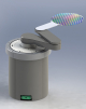
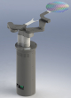
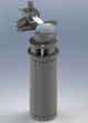
Genmark’s MiniMax™ Equipment Front End Module (EFEM) is a class 1 minienvironment system designed to maximize productivity of semiconductor processing equipment tools that require the highest level of automation.
The MiniMax™ can be customized to meet the automation requirements of any semiconductor manufacturing tool application and specified with one of the Genmark’s sophisticated and precise wafer and reticle handling robots, including the full line of patented GPR single or dual arm robots, GREX robot series, single and dual wafer aligners, FOUP/FOSB openers, reticle libraries, as well as any other customer specified equipment.
Genmark’s ECS300 Automation Software Suite is the standard product controlling the MiniMax™ system and the interface with the manufacturing equipment and the fab.
| Enclosure | |
| Base Frame | Welded steel, BOLTS compatible load ports |
| Coating | Baked powder coat |
| Fan Filter | |
| Fan Filter | Unit Per customer specification |
| Filter media | PTFE ULPA 99.99995% @ 0.1 micro meters efficiency |
| Wafer Size | up to 300mm |
| Automation | |
| Atmospheric Robot (types) | G-Rex; GB4S; GPR-GB7S; GPR-GB8; GPR-GB8-SM |
| End Effector (types) | Vacuum gripping, Edge gripping, Gravity |
| Pre-Aligner (types) | Vacuum gripping chuck; edge rgipping chuck |
| Wafer Mapping | Through-beam |
| User Interface | Keyboard, mouse, touch screen |
| Software Interface | SEMI E30, E84, E87, E90, E40, E94, E99, E118, E116 |
| Communications | Physical Properties |
| Physical Properties | |
| Length | Two load ports - 45" Three load ports - 66" Four load ports - 80" |
| Air Pressure: Relative to Cleanroom Ambient | |
| Port Closed | Spec: 0.01 +/- 0.005 inches w.c., (2.5 +/- 0.13 Pa) |
| Load/Unload | Spec: 0.01 +/- 0.005 inches w.c., (2.5 +/- 0.13 Pa) |
| ME Recovery time | < 38 sec |
| Air Flow Velocity | 90 +/- 10% ft/min, (0.45 +/- 10% m/sec) |
| Standarts Compliance | |
| SEMI | - SEMI S1-0701 - SEMI S2-1102 - SEMI S7-96 - SEMI S8-0701 - SEMI S9-1101 - SEMI S10-1296 - SEMI S13- 0298 - SEMI E15-0698 - SEMI E44-96 - SEMI E54-0997 - SEMI E57-0600 - SEMI E58-0301 - SEMI F47-0400 |
| Other Standards | CE Standards, International Sematech Integrated Minienvironment Best Design Practices. |
| Environment | |
| Cleanliness | Class 1 |
The airborne sample probe was positioned 0.5 - 1.0 inch from the sample locations, pointed toward the sample location. Where mechanical movement would create collision between he airborne probe and the moving part, the airborne sample probe was positioned 0.5 - 1.0 inch from the closest approach of that moving part.
Background counts quantify the particles due to all factors except system movement.
This includes particles from the test procedure itself.
For this test, the robot moved continuously in a simulated wafer transfer pattern.
The movement pattern was:
Met One 2100C